2nd LPT Challenge Case 2 Datasets
This page details the test case principle and instructions. To see published results, see the corresponding pages for two-pulse and time-resolved cases.
1. Physical situation
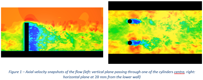
The physical situation is that of the wake caused by two cylindrical pillars placed in a turbulent boundary layer. The flow medium is air, and its bulk velocity outside the boundary layer is equal to 10 m.s-1. At the streamwise position of the cylinders, the boundary layer is approximately 60 mm thick, with a momentum Reynolds thickness equal to 4,150. Numerical simulation is performed using Monotone Integrated LES, wherein embedded propagation of virtual particles, hypothesized as fully passive tracers, is included.
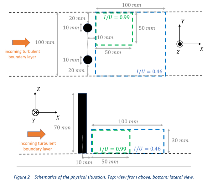
Axes X, Y and Z respectively correspond to the streamwise, spanwise and wall-normal directions (see Figure 2). Simulation is performed over an extension of 100 mm in Y, with spanwise boundary conditions. Cylinders have a diameter of 10 mm and their centres are located 25 mm from the simulation spanwise edges. For the challenge, different domains of 30 mm thickness (Z direction), starting 10 mm downstream from the cylinder centres, have been selected.
The optical setup consists of four virtual cameras which view these domains mainly from above (Z direction), onto the XY plane. They are located at the base of a square pyramid, at a height of around 0.45 m (Z direction). Edges of this base are along the X and Y axes and the edge size is equal to 0.6 m. All cameras have a 2048 x 2048 sensor with 10 µm pixel pitch, and are equipped with an f = 200 mm lens.
Among the varying parameters in this case is the ratio I/U between the volume of the intersection of the cameras' fields of view (denoted by I) and of their union (denoted by U). Value of this parameter determines whether all of the illuminated domain (and particles) are viewed by all cameras (I/U = 1), or if parts of the domain/particles are viewed only by a subset of them (I/U < 1). As depicted in Figure 2, the domain extensions in X and Y directions change depending on the I/U value: the domain is largest for I/U = 0.46, and smallest for I/U = 0.99, which are respectively the smallest and largest values for the I/U parameter in the dataset. The origin O of the coordinate system changes accordingly, as it is always supposed to be located at the centre of the domain in the X and Y directions, and at the wall (Z direction). As the camera system also adapts to the different domains, i.e. always has the same location relatively to the origin O, this allows to consider the same calibration for all cases. Note also that, in order to obtain the desired I/U values, illumination had to be cut artificially in both the X and Y directions, for all I/U > 0.46. In a sense, this amounts to using a slab for cutting in X, and to consider wind-tunnels of different spans for cutting in Y.
2. Input data
2.1. Camera calibration
Camera calibration can be performed by downloading the ASCII file LPT_CASE02_CalibPoints.txt (using the Camera Calibration link). Each line of this file contains the coordinate of a point in the domain together with its projection on the four cameras:
X Y Z x1 y1 x2 y2 x3 y3 x4 y4
where (X,Y,Z) are the point coordinates in units of mm and (xi,yi) the coordinates of its projection on camera i in units of pixel. Pixel position (0,0) corresponds to the centre of the pixel located at the top left corner of an image.
2.2. Cases and images
This test case contains both two-pulse (TP) and time-resolved (TR) image sequences. The inter-frame time is fixed at 40 µs. A constant particle image size (PSF/OTF) is used, and some typical camera noise is added on the images. Parameters explored are the seeding density, the I/U value and Mie scattering (Mie = 1 if accounted for, otherwise Mie = 0). Note that Mie scattering coefficients correspond in fact to different observation angles than that of the present setup. Indeed, the current setup would either lead to having a pair of cameras in forward scattering and the second in backward scattering, which is a situation that one would avoid in practice (case of light in the X or Y direction), or to having all cameras with the same scattering conditions (case of light in the Z direction). Instead, equivalent camera positions have been picked coresponding to different angles in the forward scattering domain (close to 30° and 45° relative to incident light).
For both TP and TR acquisition types, the parameter sweep is the following:
- Variation of seeding density for I/U = 0.99 and Mie = 0: densities equal to 0.025, 0.05, 0.08, 0.12, 0.16, 0.20 and 0.25 particles per pixel (ppp)
- Variation in I/U at 0.08 ppp, with Mie = 0: I/U values equal to 0.46, 0.59, 0.72, 0.85 (and 0.99, included in the ppp variation)
- Influence of Mie scattering at 0.08 ppp: cases with Mie = 1 at I/U = 0.99 and 0.46, to be compared with the same with Mie = 0
Images are named in the following format:
LPT_CASE02_YY_ppp_0_AAA_IU_BBB_Mie_D_IEEEE_C.tif, with:
YY: acquisition type (TR or TP)
AAA: fractional ppp value
BBB: value of I/U, multiplied by 100, with a leading 0
D: Mie accounted for (D=1) or not (D=0)
EEEE: snaphot number with leading zeros, starting from 0000
C: camera number, from 0 to 3.
In the TR case, sequences contain 50 images for ppp up to 0.16, and 100 images for higher-density cases.
3.Requested output and formatting rules for upload
Participants can choose whether they want to process the TR or the TP data, or both.
3.1. TP case
3.1.1. Mandatory cases
Results have to be submitted at least up to ppp = 0.12 included; in particular, all cases at 0.08 ppp, including those corresponding to the I/U and Mie sweeps, are mandatory. Processing as well the higher seeded cases is of course encouraged. In that case, all seeding densities up to the highest chosen one should be provided.
3.1.2. Preparing your upload
Please replicate the contents of the sample archive myAlgo_LPT_CASE02_TP.zip:
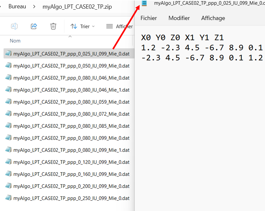 Results for each seeding density should be stored in an ASCII file with first line equal to X0 Y0 Z0 X1 Y1 Z1 followed by one line for each particle with the two measured particle positions X0, Y0, Z0 and X1, Y1, Z1 in mm for time steps t0 and t1. There is no specific convention about number formatting.
- File naming convention (as above): myAlgo_LPT_CASE02_TP_ppp_0_AAA_IU_BBB_Mie_D.dat, with AAA the fractional value of seeding density in ppp and "myAlgo" a string that can be chosen freely, but without any space in it.
- Once your files are ready, as in the example above, please zip them directly into a single archive. Please make sure that you do not zip a folder containing the results, as this will result in the submission being rejected.
3.2. TR case
3.1.1. Mandatory cases
Results have to be submitted at least up to ppp = 0.12 included; in particular, all cases at 0.08 ppp, including those corresponding to the I/U and Mie sweeps, are mandatory. Processing as well the higher seeded cases is of course encouraged. In that case, all seeding densities up to the highest chosen one should be provided.
Important: the requested snapshot number depends on the seeding density value: time step 25 (images ‘_I0024’) shoud be provided for ppp ≤ 0.16, while time step 50 (images ‘_I0024’) is expected for ppp ≥ 0.2.
3.1.2. Preparing your upload
Please replicate the contents of the sample archive myAlgo_LPT_CASE02_TR.zip:
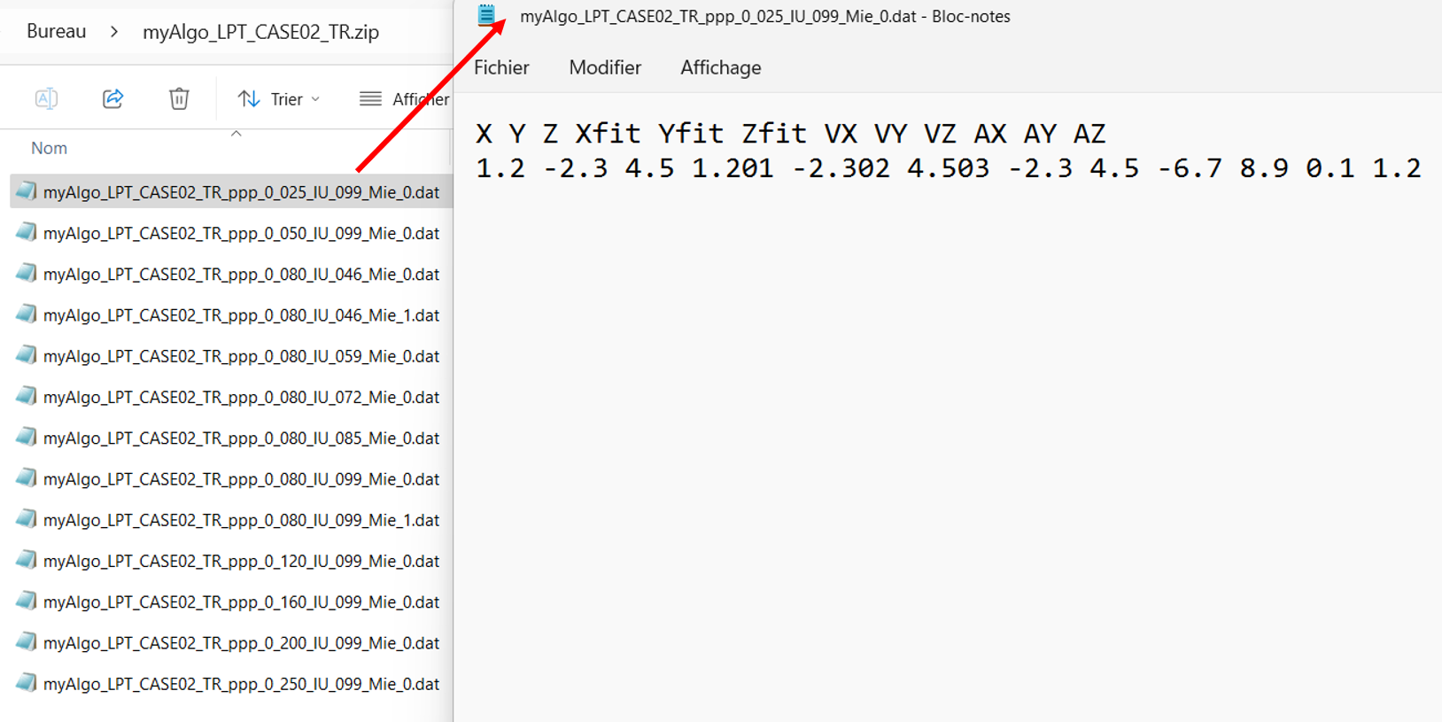 Results for each seeding density should be stored in an ASCII file with first line equal to X Y Z Xfit Yfit Zfit VX VY VZ AX AY AZ followed by one line for each particle track with raw position X, Y, Z in mm, fitted position (i.e. associated to the estimation of velocity and acceleration) Xfit, Yfit, Zfit in mm, the velocity VX, VY, VZ in m/s, and the acceleration AX, AY, AZ in m/s2, all calculated at time step 25 or 50 depending on the seeding density of the case. There is no specific convention about number formatting.
- File naming convention (as above): myAlgo_LPT_CASE02_TR_ppp_0_AAA_IU_BBB_Mie_D.dat, with AAA the fractional value of seeding density in ppp and "myAlgo" a string that can be chosen freely, but without any space in it.
- Once your files are ready, as in the example above, please zip them directly into a single archive. Please make sure that you do not zip a folder containing the results, as this will result in the submission being rejected.
3.3. Upload form
Once your zip archive is ready, clicking on "Submit TP results" or on "Submit TR results" will open a form allowing you to upload a file containing your results.
The upload form should also be filled with the following information, which is used for result presentation only if you choose to publish your result based on the evaluation sent by email:
- List of authors (default: submitter name)
- Authors' institution(s) (default: submitter institution)
- Optional: departement / team (default: submitter's departement / team)
- Algorithm's short name or acronym
- Algorithm's full name
- Optional: URL address of the publication on your algorithm, or of a webpage describing it
For these fields, note that rules apply, in terms of maximum length and/or authorized characters. These are displayed on the form in the explanatory text of each field. In particular, commas are not allowed in any of the above fields.
Contact in case of questions: Benjamin Leclaire, ONERA: benjamin.leclaire@onera.fr